
Theory of Operation
The term “nuclear reactor” is somewhat sensationalist. It invokes images of nuclear weapons and dirty bombs. However, fusion is very different than fission. Fusion is not dangerous (relatively speaking); fission is. Fission splits a heavy nucleus into two smaller nuclei, causing a chain reaction that releases enormous amounts of energy. Fusion, on the other hand, involves combining two small nuclei to create a larger one, and does not cause a chain reaction.
The purpose of a fusor is to use nuclear fusion to produce fast neutrons. The apparatus is nothing more than an electrostatically accelerated spherical deuteron collider.
The inertial electrostatic confinement (IEC) fusor consists of five parts: a vacuum system, a high voltage apparatus, a tungsten geodesic cage, a deuterium input line, and a neutron detector.
The main chamber is vacuum tight and is made of stainless steel. This chamber has several ports which allow for the removal of air, the flow of deuterium, and the determination of pressure, among other things. Critically, the chamber contains a tungsten grid, mounted on an insulated electrical feedthrough.
Firstly, the apparatus has all of the air removed. The pressure is around .6 mTorr (8E-7 atm). Then, deuterium flows back into the chamber to a pressure of around 7 mTorr (1E-5 atm). Next, -30 kV of electricity at 25mA is applied to the tungsten grid in the center of the chamber.
This electricity does two things: it ionizes the deuterium atoms, and creates an electrostatic gradient from the chamber walls (0V) to the central grid ( -30000V). Since the deuterium atoms had their electrons stripped away, they become positively charged deuterons. These deuterons accelerate radially inward toward the negatively charged grid.
Ideally, two 30 keV deuterons accelerate from opposite ends of the fusor collide (there is columbic repulsion, but the strong force takes over), fusing together.
Deuteron + Deuteron = Helium-3 (.82 MeV) + neutron (2.45 MeV) [50%]
Deuteron + Deuteron = Tritium (1.01 meV) + proton (3.02 MeV) [50%]
According to these two equations, 50% of all fusions that occur within the chamber produce a neutron. Because the fast neutron is neutral, it passes through the stainless steel chamber. Some of these neutrons, after losing energy to a moderator (they become thermal neutrons), hit a helium-3 proportional counter. This device measures the number of neutrons that hit it.
The neutrons can now be used for scientific experimentation.
As you may imagine, fusors do fusion very badly. They can barely scratch 1 million neutrons per second, out of the 10E15 atoms in the chamber.
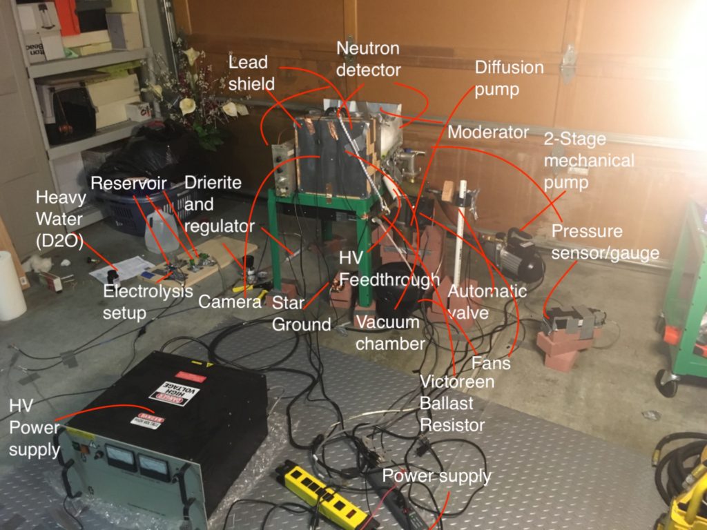
My Fusor
Vacuum system
The first step in the road to fusion is achieving a vacuum (no small feat!). Without a proper vacuum, it would be impossible to operate the fusor.
My vacuum system consists of a convectron gauge tube, an air cooled oil diffusion pump, and a two stage mechanical backing pump. There is a gate valve between the pumps and the chamber. The mechanical pump first pumps down to around 100 mTorr. Then, the oil diffusion pump is turned on, and it refines the vacuum down to .7 mTorr.
Everything must be completely vacuum tight in order to achieve such high vacuums. I use viton elastomer gaskets for all of my conflat flange connections. I have a series of swagelok adaptors on my mechanical pump, which connects to a vacuum hose, which connects to the diffusion pump. Since the gate valve and my 90 elbow are both O-ring seals, I machined a piece of titanium to fit between them to allow a proper seal The convectron is attached to the elbow.
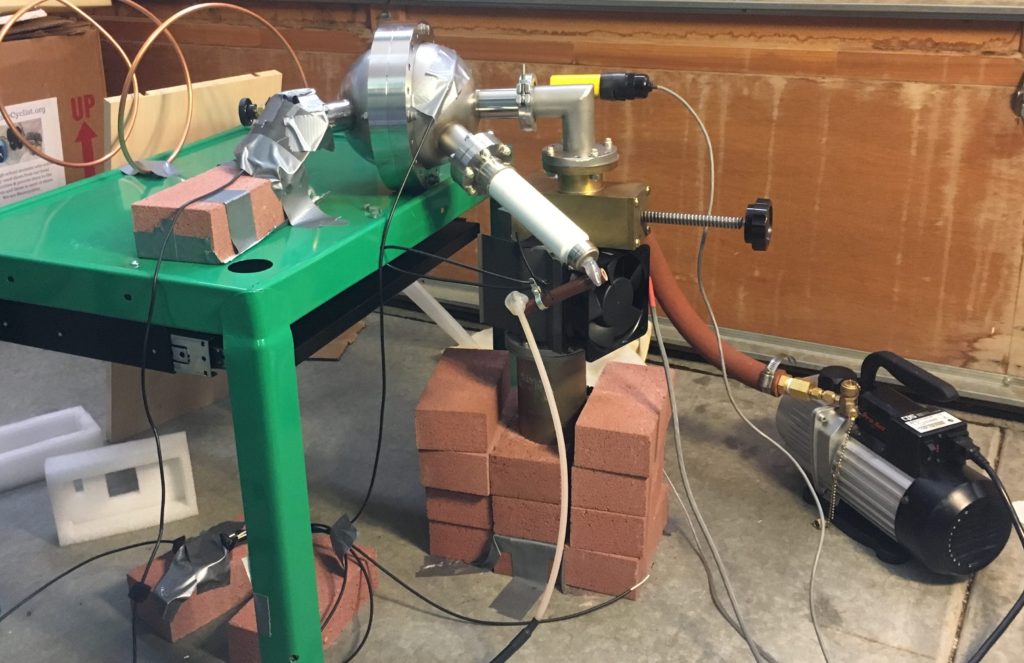
My vacuum setup. There is also a viewport attached to one of the CF nipples. An HV feedthrough is attached to the other.
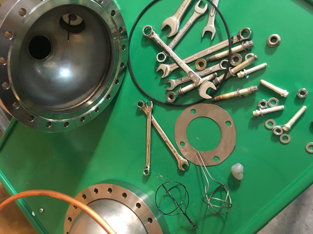
The inside of the chamber. I dismantled it in order to replace the tungsten grid. You can see the viton gasket I use, along with the titanium I machined for the O ring. You can also see the conductive stalk that the grid is mounted on.
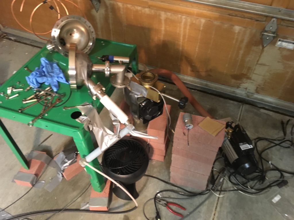
Here is the dissassembled vacuum system.
Deuterium electrolysis
Unfortunately, I was not able to acquire any pure deuterium gas. I resorted to making my own via electrolysis of heavy water. I use 2 volts of electricity from a DC supply to split molecules of D20. This is done in a PEM cell, which has a membrane that splits the D2 and the O2.
The deuterium then runs through a series of reservoirs, and passes through a pressure regulator. This allows the PEM cell to stay at atmosphere levels, without compromising the vacuum of the chamber. It then passes through a tube of drierite, which removes humidity from the gas.
Lastly, the deuterium is admitted into the chamber via a swagelok needle leak valve.
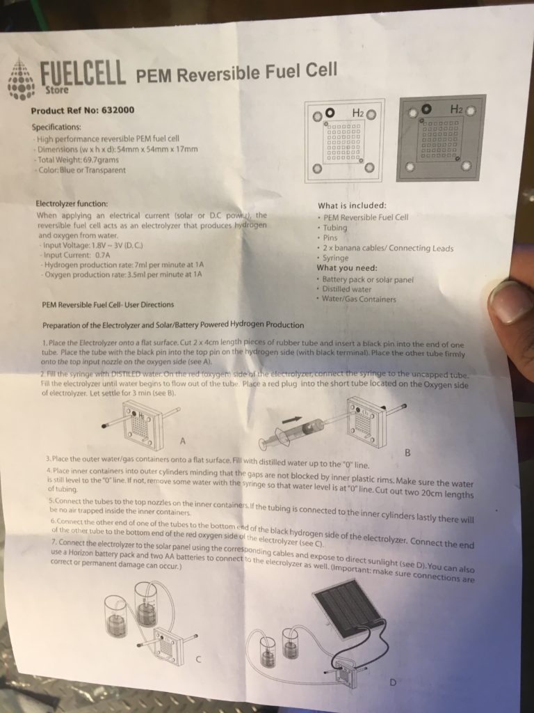
The instructions for the PEM cell.
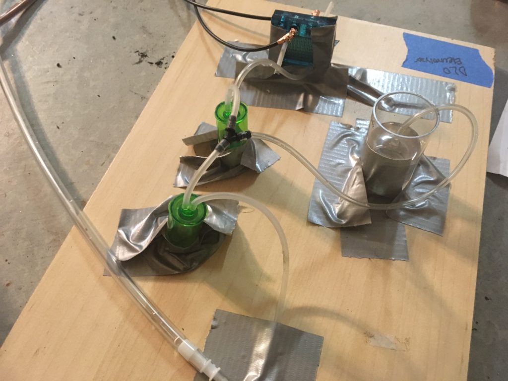
The apparatus for electrolysis. As you can see, the deuterium gas passes through several reservoirs and is stored in the clear beaker.
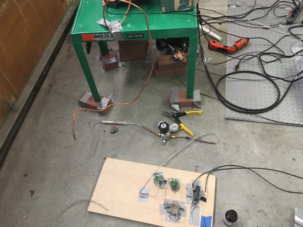
Here is the complete setup, with the regulator and the tube of drierite.
Tungsten grid
I made several loops of tungsten, and spot welded it together. This geodesic was then mounted on the electrical feedthrough.
Unfortunately, the first grid I made disintegrated after I applied too much voltage. I replaced it 1.5 mm tungsten wire. This was a huge pain to machine. The tungsten was very brittle, and kept breaking.
It was nearly impossible to spot weld it together. My friend, Stephen Ho, worked with me to do so. He modified a stud welder for use as a spot welder, and we managed to weld the very thick tungsten together.
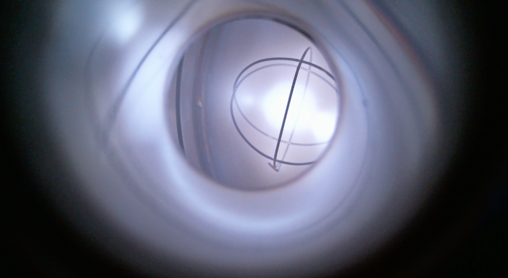
The old grid, creating a plasma at 5kV.
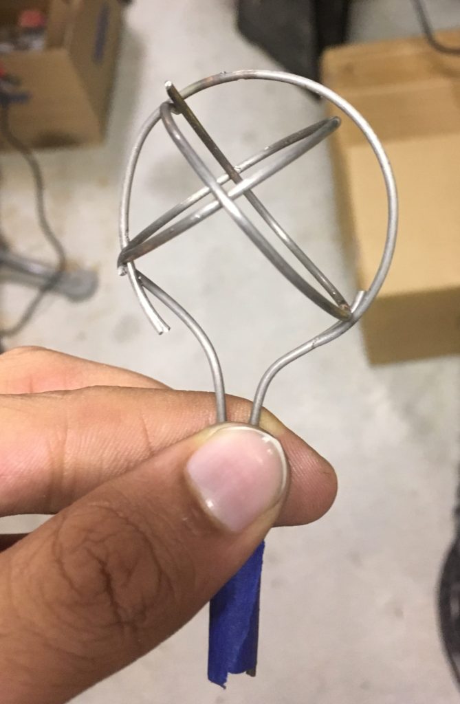
The new grid we made.
Input power
This machine is what causes fusion to occur. It is a Glassman high voltage power supply. I purchased it from eBay. Unfortunately, there are no schematics for it online, so I am unable to modify it to raise the voltage.
I am currently working on alternate power supplies so I can raise the voltage to 50kV.
Ohm’s law says that Voltage = Current * Resistance. The resistance is proportional to the pressure in the chamber. If the pressure is low enough, then the power supply will be voltage limited, rather than current limited.
Because the resistance and therefore the voltage can vary rapidly, it is necessary to protect the power supply from power fluctuations. This is done with a resistor connecting the power supply to the feedthrough. This resistor protects the power supply from dead shorts.
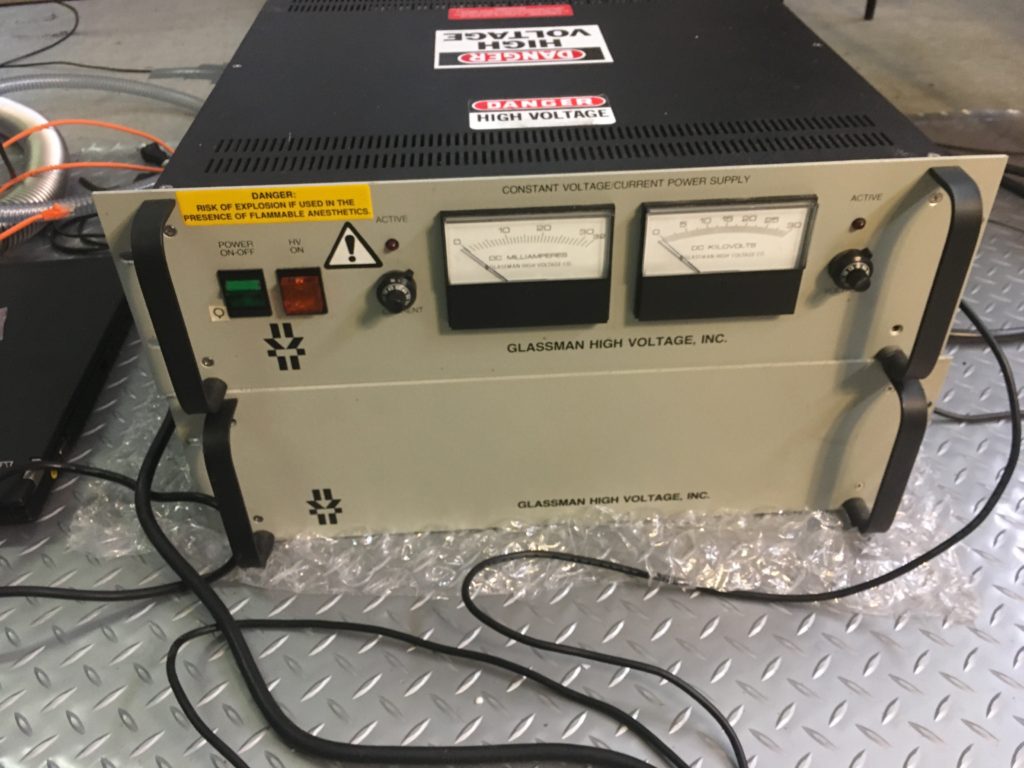
The front of the machine, where I control the voltage and current.
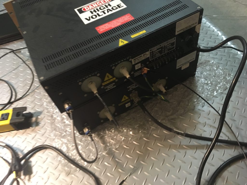
The rear side of the power supply. Note the multitude of cables connecting the master unit to the slave. Also note the grounding connection.
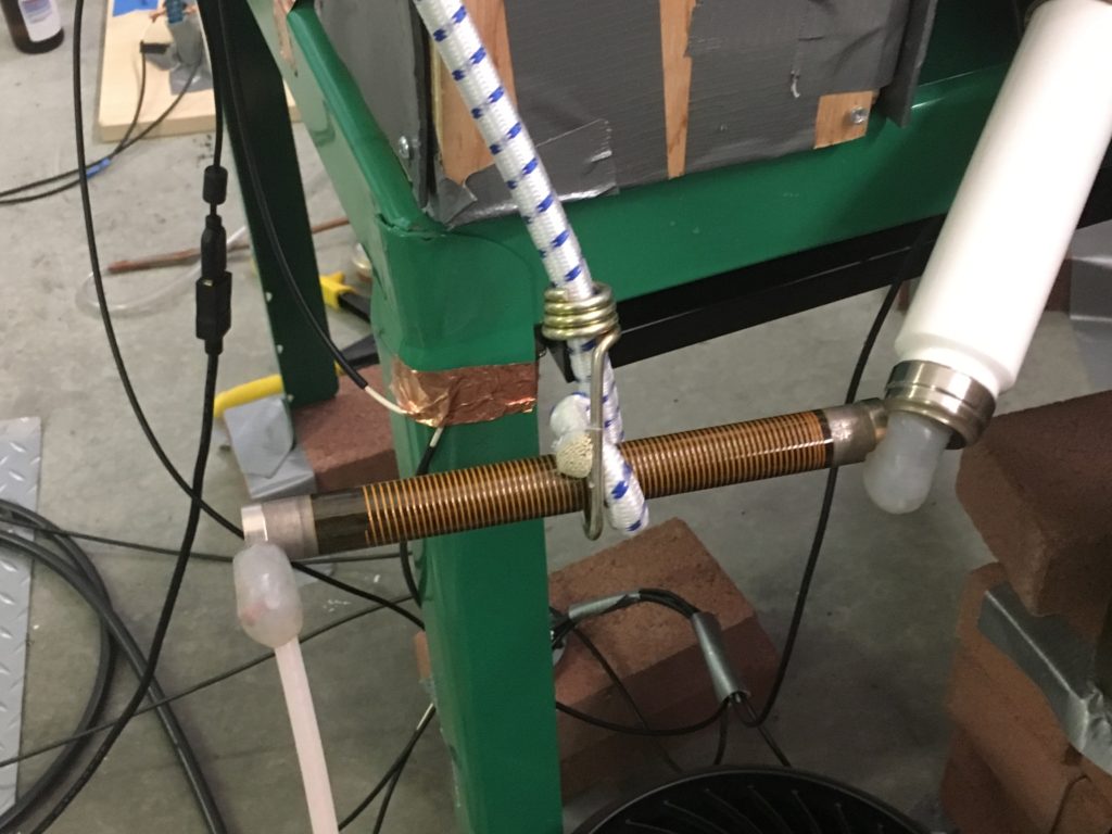
I use a high resistance (200kOhm) victoreen resistor as my ballasting resistor. It is rated to 50kV. Note the 10kV silicone gel on both connections. This is supposed to prevent arcing up to 10kV applied. The resistor is held up with an elastic cord attached to my radiation shield.
Neutron detection system
The last major system is the neutron detection system. Its purpose is to detect the number of thermal neutrons that hit a helium-3 proportional tube. The tube is held to a certain bias voltage (1600V). A digital oscilloscope then measures, discriminates, amplifies, and records the signal. It is hooked up to a computer, which then generates a graph of counts per minute (CPM) over time.
A proportional counter can only detect thermal (slow) neutrons. All of the neutrons that exit the fusion chamber are fast neutrons (2.45 MeV). In order to slow the neutrons down, a material known as a moderator must be used. A moderator absorbs some of the energy of the neutron, slowing it down to a thermal neutron.
Paraffin wax is one such moderator. HDPE is another. I incorporated blocks of paraffin wax into the faraday cage that surrounds the tube, and I put sheets of HDPE between the chamber and the proportional counter. This means that a fair amount of the fast neutrons will be moderated and detected by my apparatus.
Unfortunately, both the wiring and the proportional tube are susceptible to electrical noise. A fusor generates a lot of electrical noise. I therefore made a faraday cage around the He-3 tube to protect it from the noise. The cage was then grounded.
Here, I am testing the apparatus. It did not work properly, because the He-3 tube was faulty. I contacted the seller, who sent a replacement tube. This shows the basic wiring of the apparatus.
This is the neutron detector as it was during my fusion run. As you can see, the cage is grounded, as is the wiring. It is also covered in lead to prevent gamma rays or x-rays from interfering with my data.
Radiation shielding
The only three things to exit the chamber are x-rays (hazardous at >40kV applied), gamma rays, and neutrons. The x-rays and gamma rays are eliminated with proper lead shielding. The level of neutron flux is so low that it poses no health hazard. In addition, the inverse square law (radiation falls off as the square of the distance) protects the public. Even so, I have placed neutron absorbing materials around the fusor.
Since I am only working at voltages up to 30 kV, the amount of lead shielding I have is somewhat overkill. In addition, since I only have neutron counts in the thousands, they are completely harmless.
However, as I am working to retrofit my system to go up to 50kV, having this much shielding is necessary. It’s always better to be safe than sorry.
It is difficult to see here, but under all of the duct tape, there is an entire sheet of 1/8th inch lead surrounding the fusor. This stops any x-rays or gamma rays from exiting the device.
The wood block on the left has lead on both faces. It is filled with a mixture of borax and paraffin wax to absorb and moderate the neutrons. The plastic bag is also filled with borax powder to further absorb neutrons. This, in conjunction with the 1/8″ lead sheeting, protects me from any radiation.
Misc.
Miscellaneous parts of the fusor.
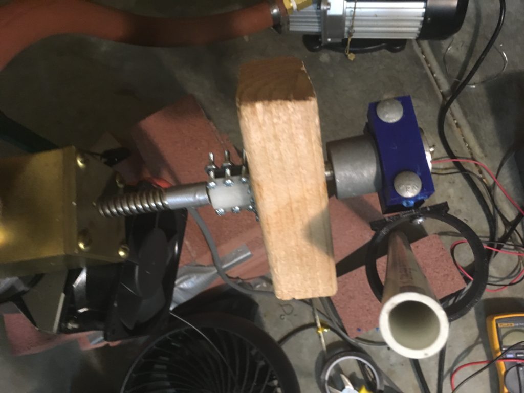
I replaced the functioning handle on my gate valve with an electric one. I wanted to control the pressure remotely. It was far more complicated than I initially anticipated. The wood would not stay on the valve screw, so I had to 3D print a part to hold it there. In addition, instead of turning the valve, the motor would instead turn its body. I had to 3D print a jig to hold it in place with a piece of PVC.
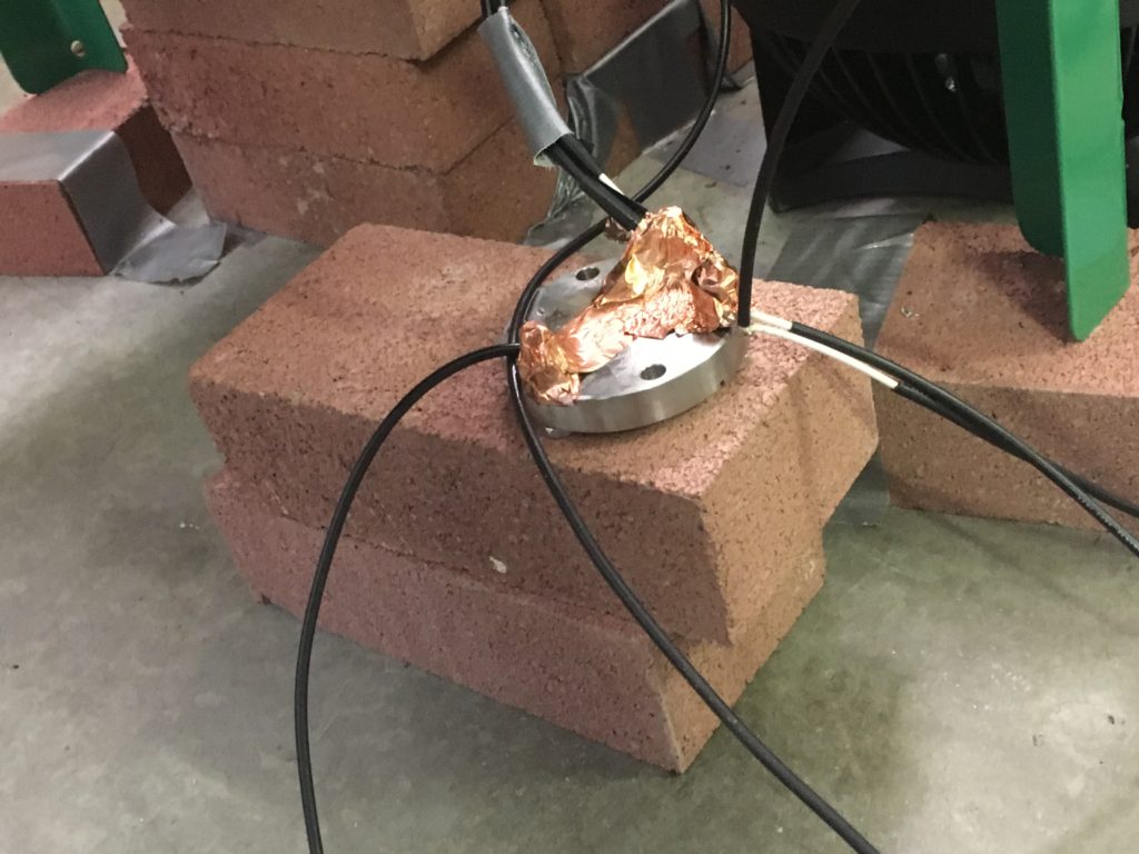
STAR grounding is important for safety in a functioning fusor. Because the resistance of the vacuum can change quickly, shorts are bound to occur. By having everything STAR grounded, nothing gets damaged, and RF noise is decreased. This is the point I chose as my ground, and it has a single cable running to my house ground.
Results and Discussion
The data I gather from the oscilloscope, and what it tells me.
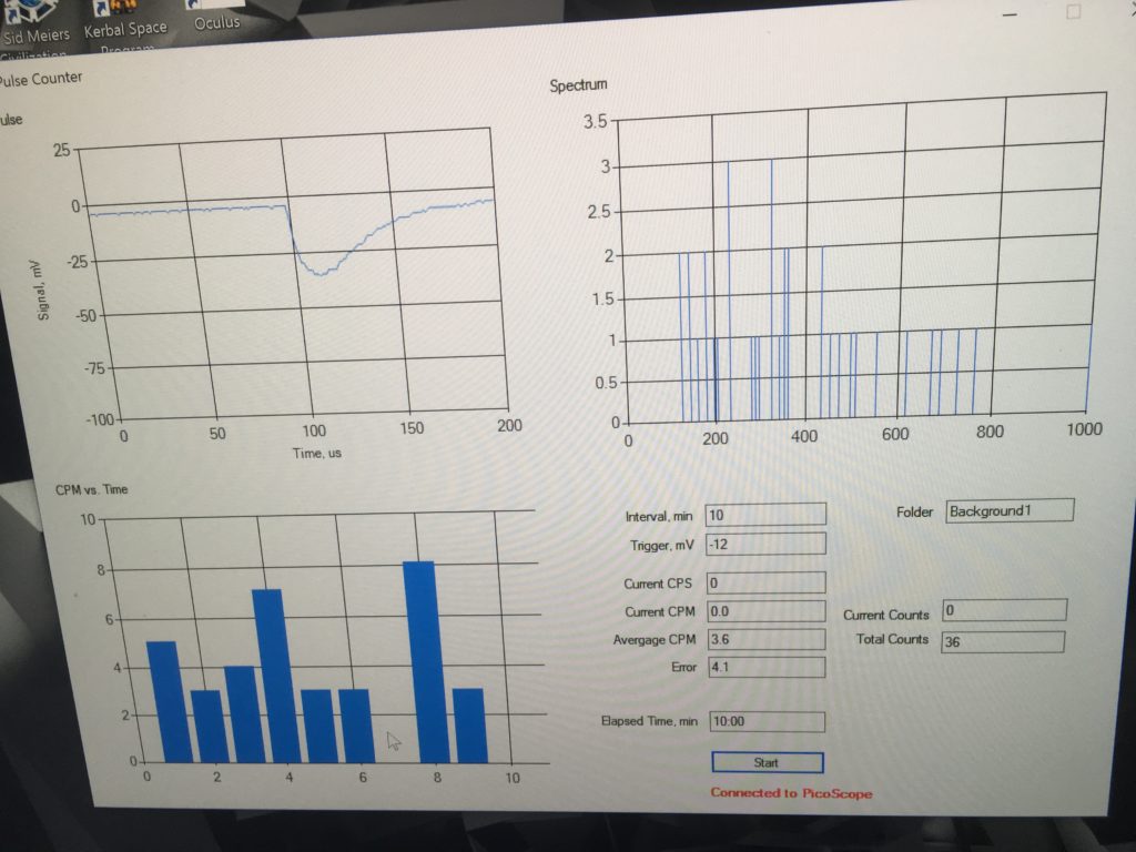
The atmospheric neutron counts in Fremont, CA. I believe this is reasonably accurate. On average, 3.6 neutrons were detected per minute.
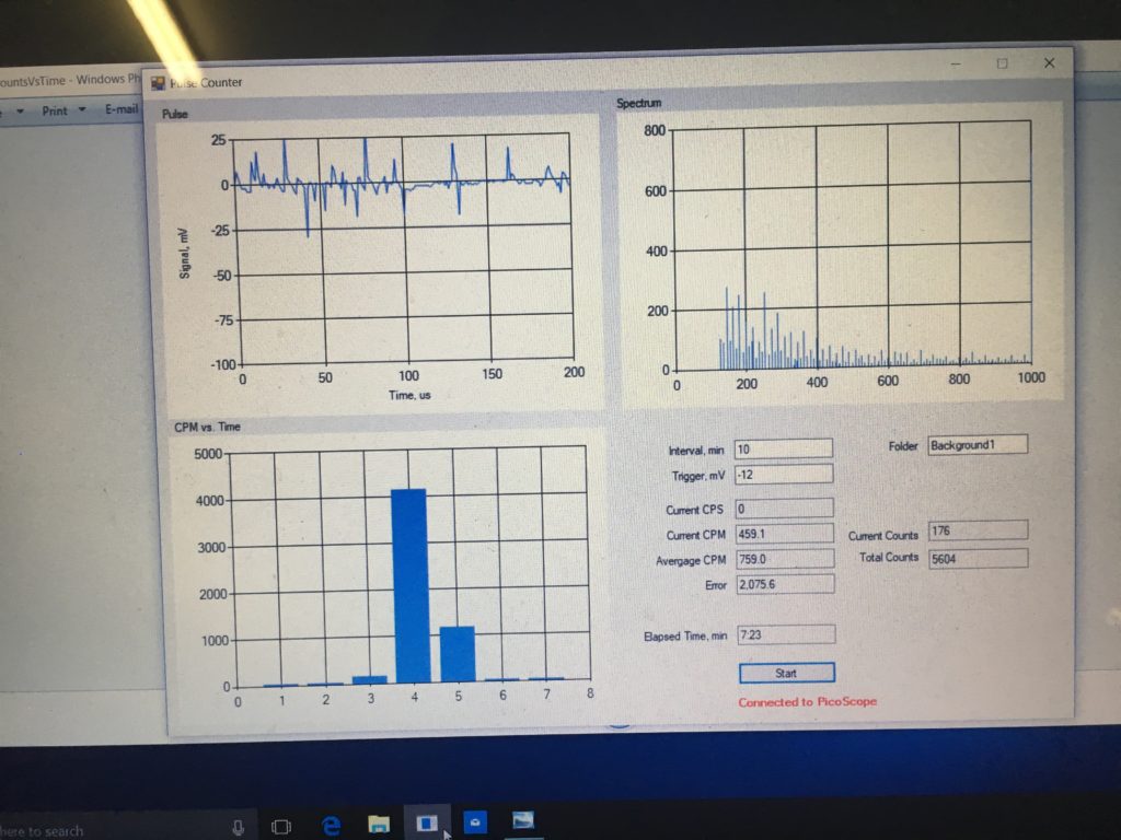
Spectrum gathered with fusion run #1.
Around 300 CPM was consistently due to RF noise. The reason for the peaks at minute numbers 4 and 5 was due to the high voltage in a deuterium rich environment causing fusion to occur. The levels of deuterium in the chamber were lowered after minute 4, which is why minute 5’s neutron count is far lower in comparison.
More info:
Open Source Fusor Research Consortium v3